Objective
In lab 3, I learned how to use I2C to communicate with two Time of Flight (ToF) sensors. I also learned to increase the speed of communication.
Prelab
According to the datasheet, the I2C sensor address was 0x52.
Because both of the ToF sensors use the same I2C address by default, I cannot just plug them in to read from both. Thus, to use two ToF sensors, there were two possible methods.
Method 1: Change the address
To use this option, I would have to change the address of both of the ToF sensors programmatically. With this, I would be able to receive data from both ToF sensors simultaneously and the delay between readings from the sensors would be reduced. However, this would require reprogramming the I2C addresses every time the Artemis is powered on, creating a longer initial setup time.
Method 2: Use the shutdown pin
To use this option, I would enable the shutdown on one of the sensors to power it off so that the other could be read. This method would save power, but it would require a delay between readings from the different sensors due to the additional logic. Additionally, we would not be able to request readings from the sensors simultaneously.
I decided to programmatically change the addresses of the ToF sensors rather than use the shutdown pin.
Since we are using two ToF sensors, the different combinations of sensor placements must be considered. At least one ToF sensor will be at the front of the robot, due to the general forward motion of the robot. This is necessary to avoid obstacles while driving forward. The second ToF sensor has some different possibilities for placement. For example, it can placed be on the side of the robot, making it so that the robot can see on one side in addition to in front. However, this means that the other side of the robot will not gain the same "vision," making it vulnerable to obstacles on the blind side. However, this would be useful if the robot needs to follow a wall on the side with the sensor. Another possibility would be to place both sensors on the front of the robot. This would allow the range of vision to be wiider in the front, and the sensor overlap may increase the accuracy of the distance reading. Another option would be to put a sensor on the back or top of the robot, providing information when the robot flips or backs up. However, this would not be optimal in most other situations, as there would not be many situations where the data uses this data.
I decided to place the sensors on the front and side of the robot, so I soldered a long connector and short connector to the boards.
The First ToF Sensor
The following image shows one ToF sensor attached to the QWIIC breakout board.
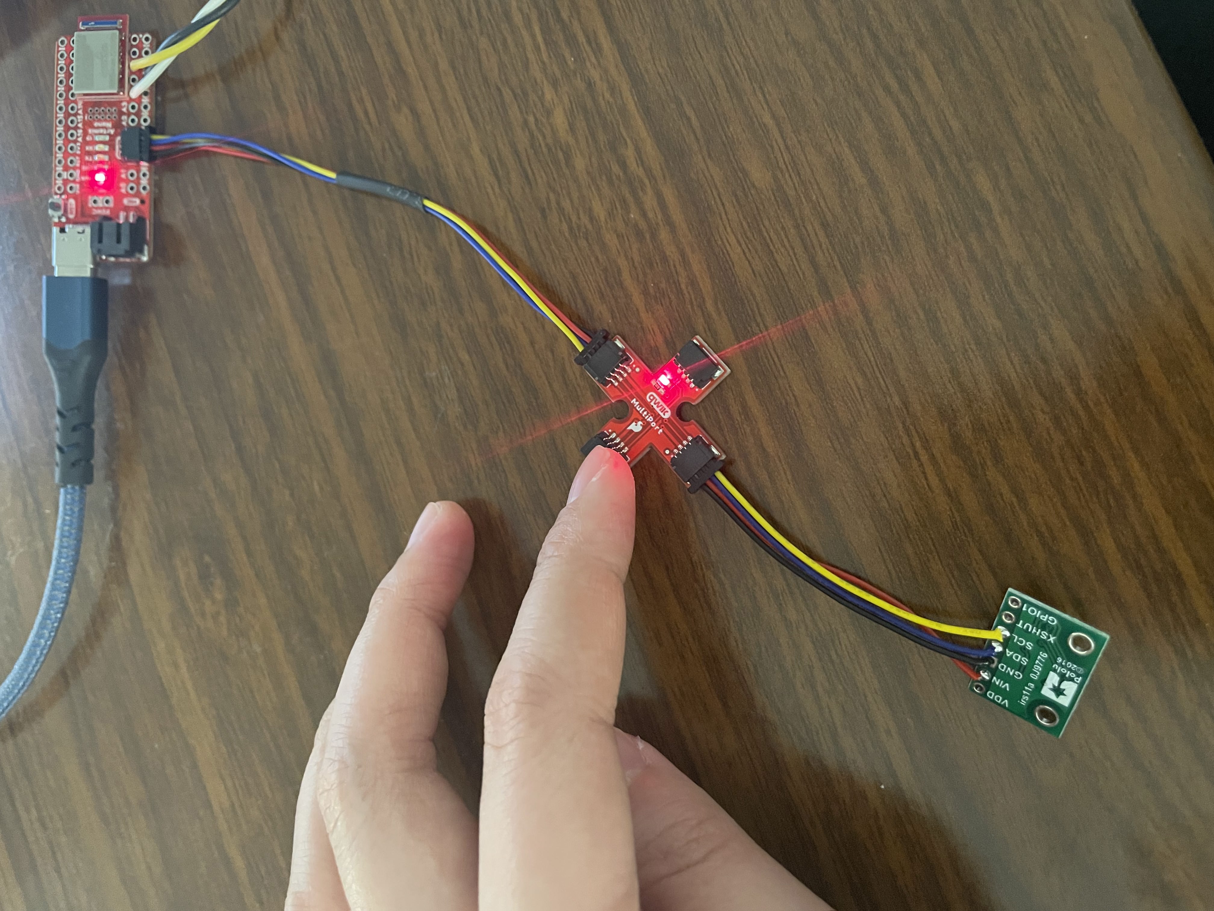
Note that I later added a wire connecting the shutdown pin of the sensor to pin 7 on the Artemis.
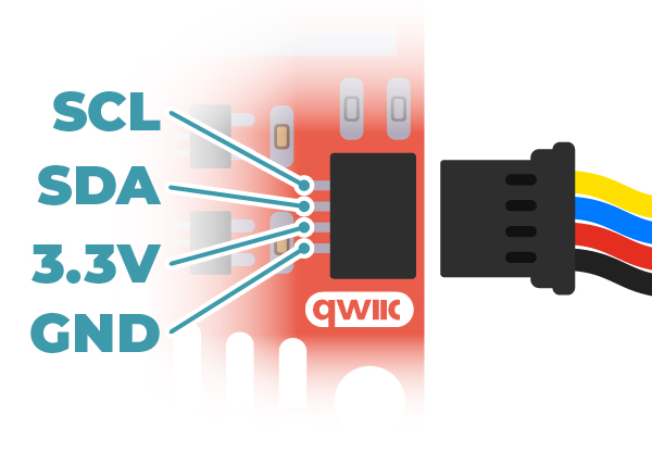
To determine which wires corresponded with SDA and SCL, I referenced the following diagram from the QWIIC documentation:
The I2C address found by the Artemis is as follows:
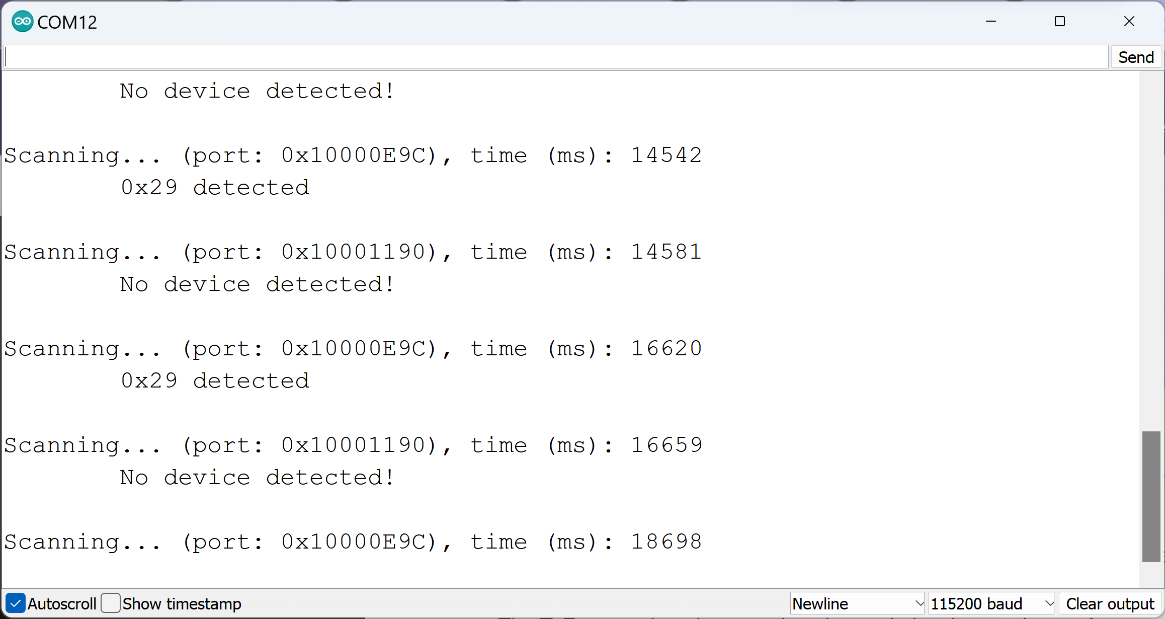
This was the expected 0x52 value right-shifted by 1, so this is reasonable, as the last bit is the read/write bit.
The three modes were as follows:
.setDistanceModeShort(); //1.3m .setDistanceModeMedium(); //3m .setDistanceModeLong(); //4m, Default
These functions will optimize the sensor for different ranges by improving the accuracy. The comments for each of the different modes shows the distances that it is most useful for (1.3m, 3m, 4m). In this lab, I used the .setDistanceModeShort mode.
I then ran the Example1_ReadDistance example and conducted a series of tests. The test setup is shown below:
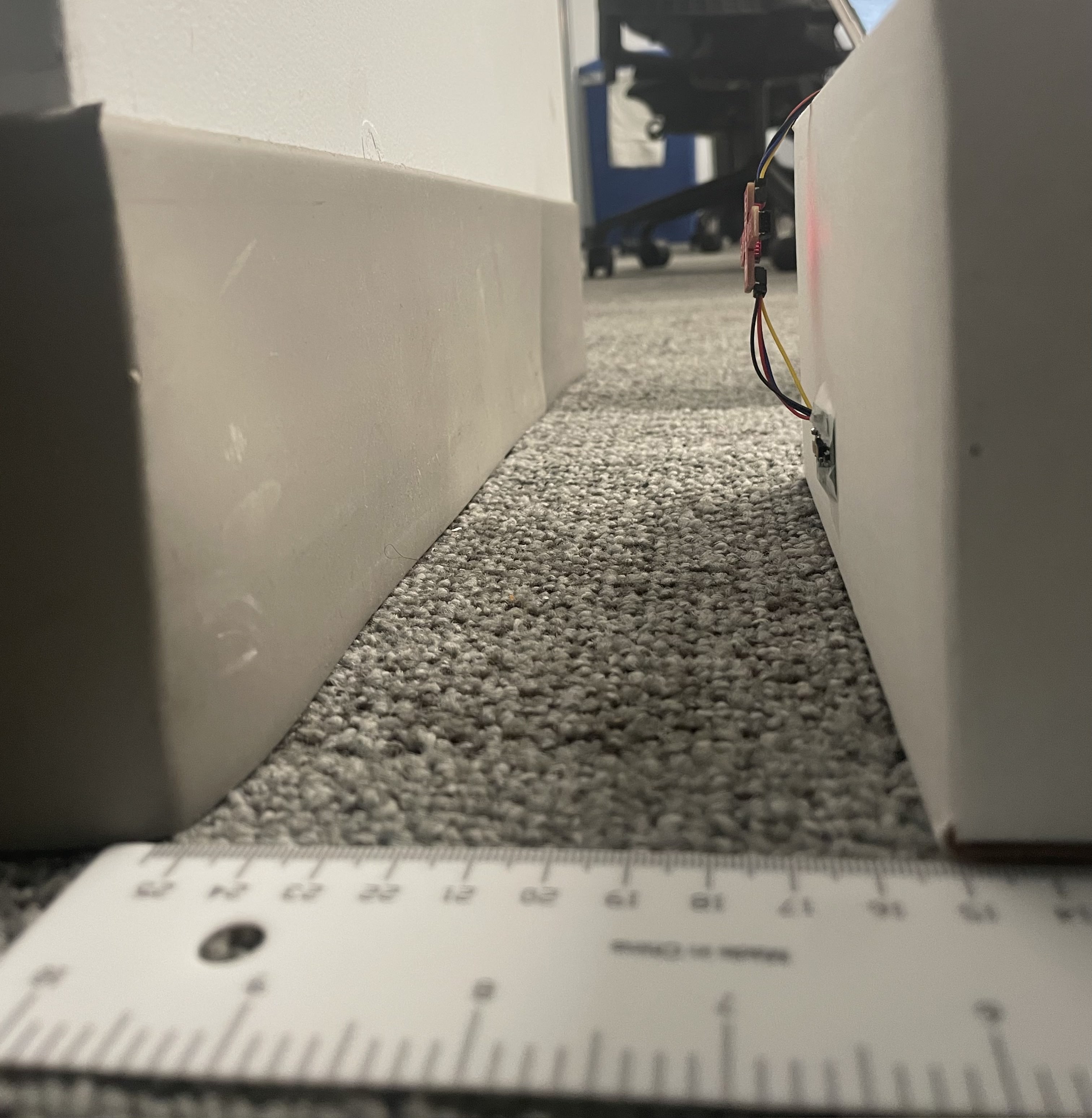
I moved the sensor by 15cm between 5cm and 135cm (1.35m, just out of the range of the short distance mode range) and collected 100 samples at each point. The results are seen in the plots below:
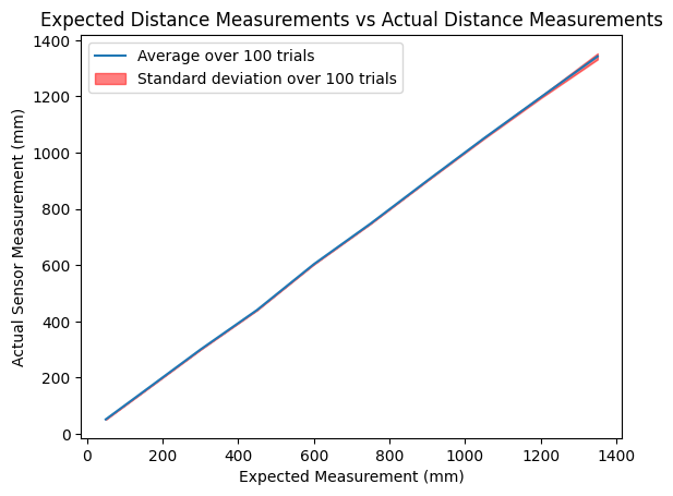
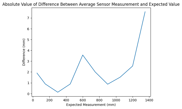
These first plot looked at the accuracy of the measurements. As one can see, the average value over the trials closely matched that of the expected values. For the distances within the range of the sensor (less than 1.3m in short distance mode), the difference between the actual and expected values were very close (within 4mm), and were still relatively small (less than 8mm) for the data point outside of the sensor range.
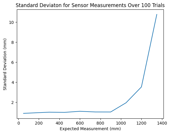
This plot demonstrates the reliability of the sensor. Over 100 trials, the standard deviation was extremely small at each distance point. It increased as the distances increased and became exponentially larger once the sensor was out of the 1.3m range, which is to be expected. However, these results prove that this sensor is both accurate and reliable within the range set by the mode.
Multiple Sensors
As mentioned before, I decided to programmatically change the addresses of the ToF sensors. To do this, I pulled the shutdown signal low on the first ToF sensor and reassigned the address of the second sensor to be 0x20. This address was arbitrarily chosen.
Simultaneous reading from both sensors is shown below:
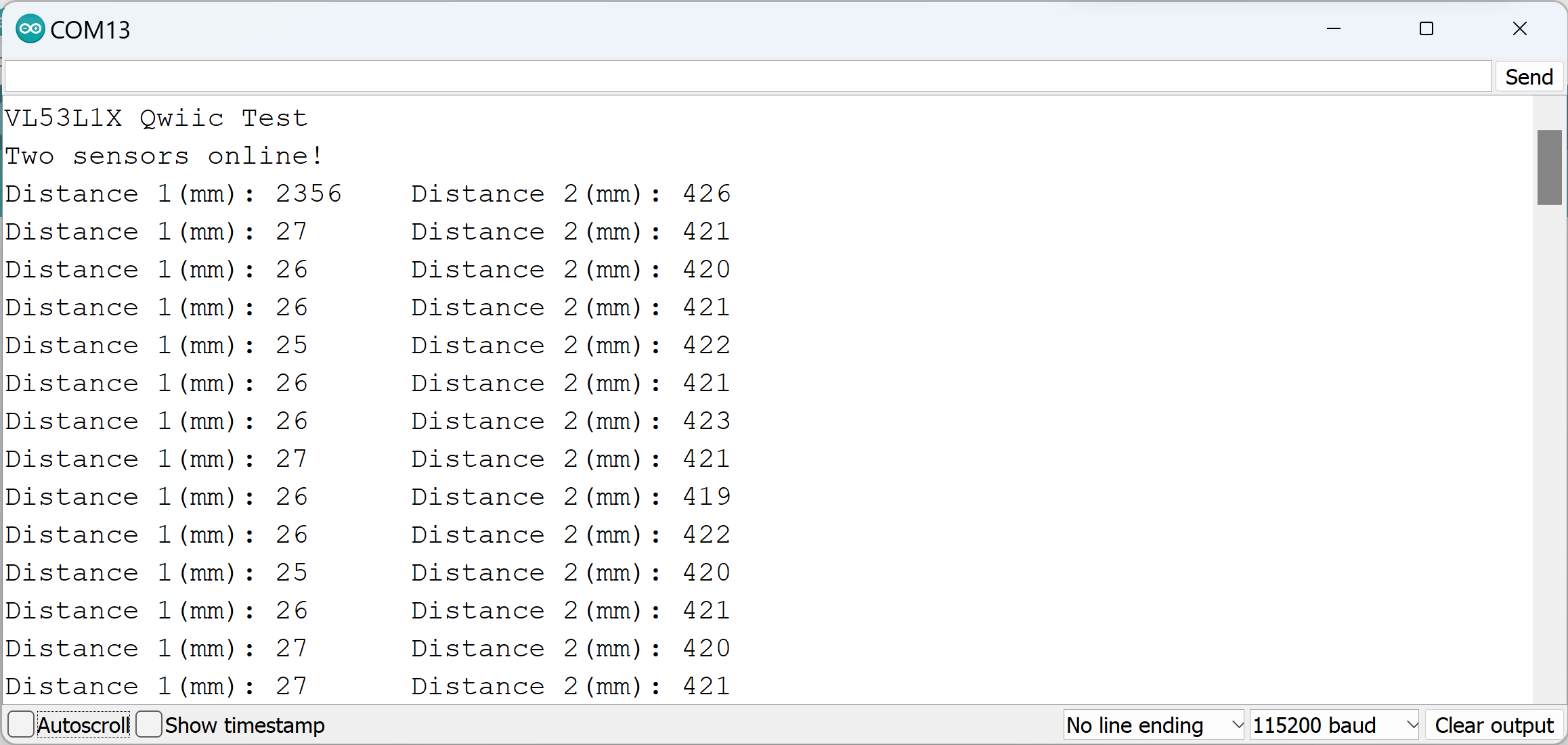
Thus, I was able to determine that I had both set up and read from both sensors correctly.
Data Speed
In this portion of the lab looked at the speed of data coming from the ToF sensors. I used the following code snippet to print the time in milliseconds and sensor readings as quickly as they were available.
With this, I found that the speed of the ToF sensor readings was significantly slower than the milliseconds readings.