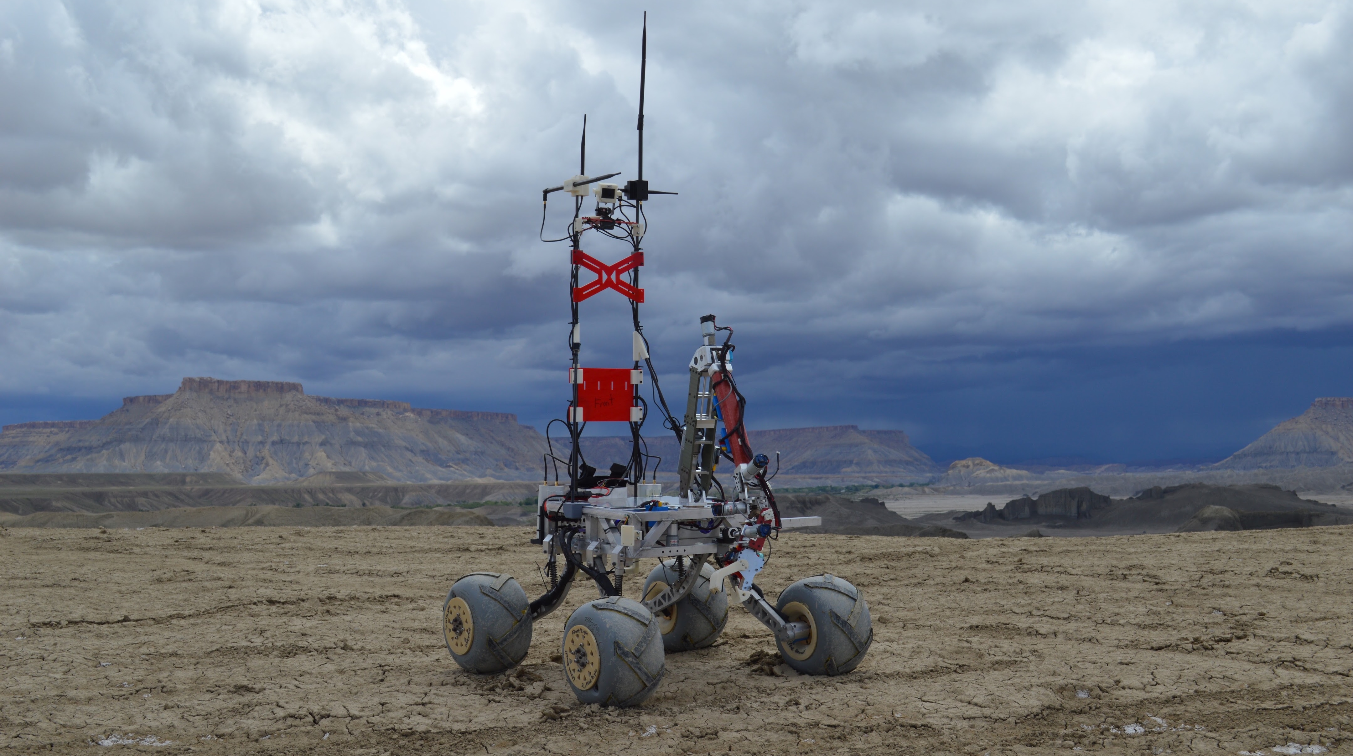
Cornell Mars Rover
Cornell Mars Rover (CMR) is a project team that designs and builds a semi-autonomous rover to compete in the annual University Rover Challenge. During my time at CMR, I designed, fabricated, and tested custom printed circuit boards to interface with the system. Additionally, I also designed the custom firmware (written in C) that was uploaded onto the PIC32MX530F128H microcontroller. In my senior year, I became the Electrical Subteam Lead, where I learned invaluable leadership skills.
2018-2019
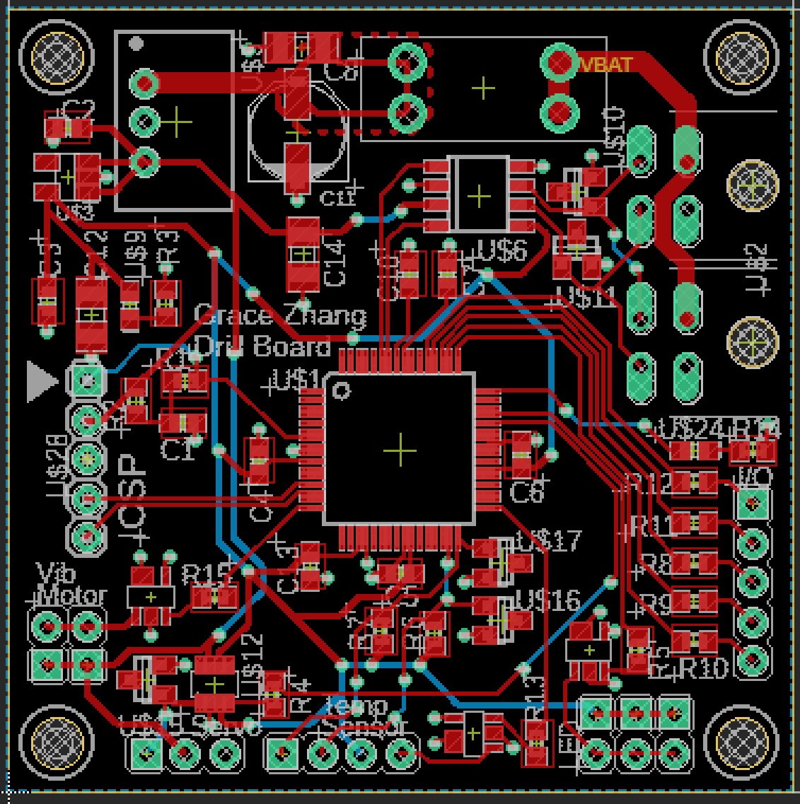
During my freshman year, I was in charge of designing the Drill Board, which was used for the Astrotech system to collect soil and read sensor data about the environment.
2019-2021
Overview
In my sophomore and junior years, I designed the motor controller board for the brushed DC motors.
The distributed tasks board (DTB) is a combination of a logic board and a power board stacked together, responsible for controlling motors on the rover. It communicates with the existing Central Communications Board over the CAN bus. Because the rover started using both brushed and brushless DC motors, the DTB needed to be redesigned to accommodate both. The brushed DC high power board is responsible for providing power to the DTB logic board and driving brushed DC motors.
Design Process
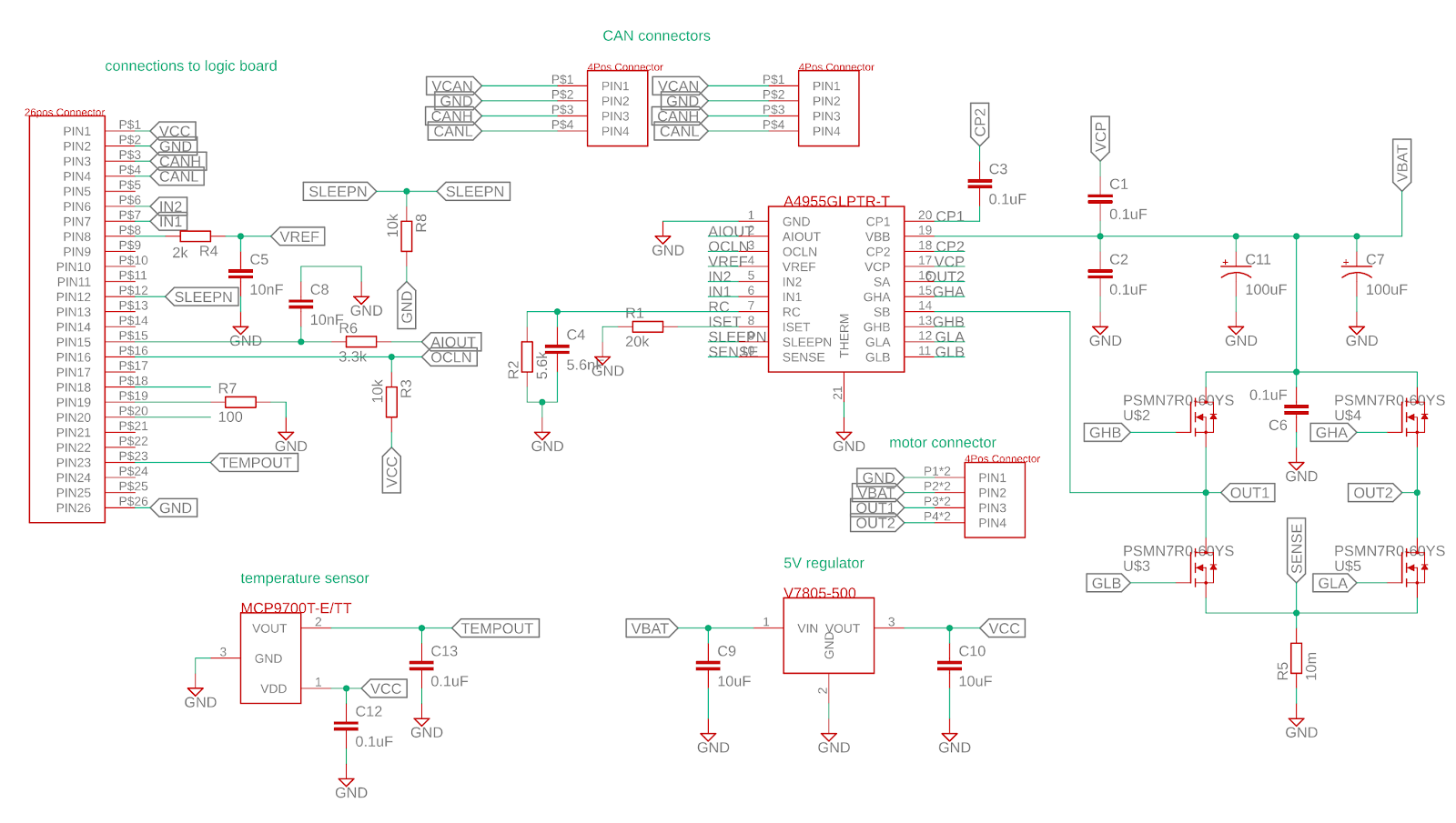
The design started with the motor driver. There was already a driver in consideration ⎯ the A4955 ⎯ that was able to run off the battery voltage and had current sensing integrated on the chip. Using the functional block diagram from the datasheet, all that was left to do for the H-bridge was choosing the correct values for the FETs, resistors, and capacitors.
The size of the FETs was determined by the amount of current it needed to supply. Additionally, since the A4955 provides gate drive for an all N-channel external bridge, the FETs had to be N-channel. The chosen FET was N-channel and rated for 60V and 89A. The rest of the components, such as capacitors and resistors, were calculated from the information given on the datasheet as well as the specifications of the microcontroller on the logic board.
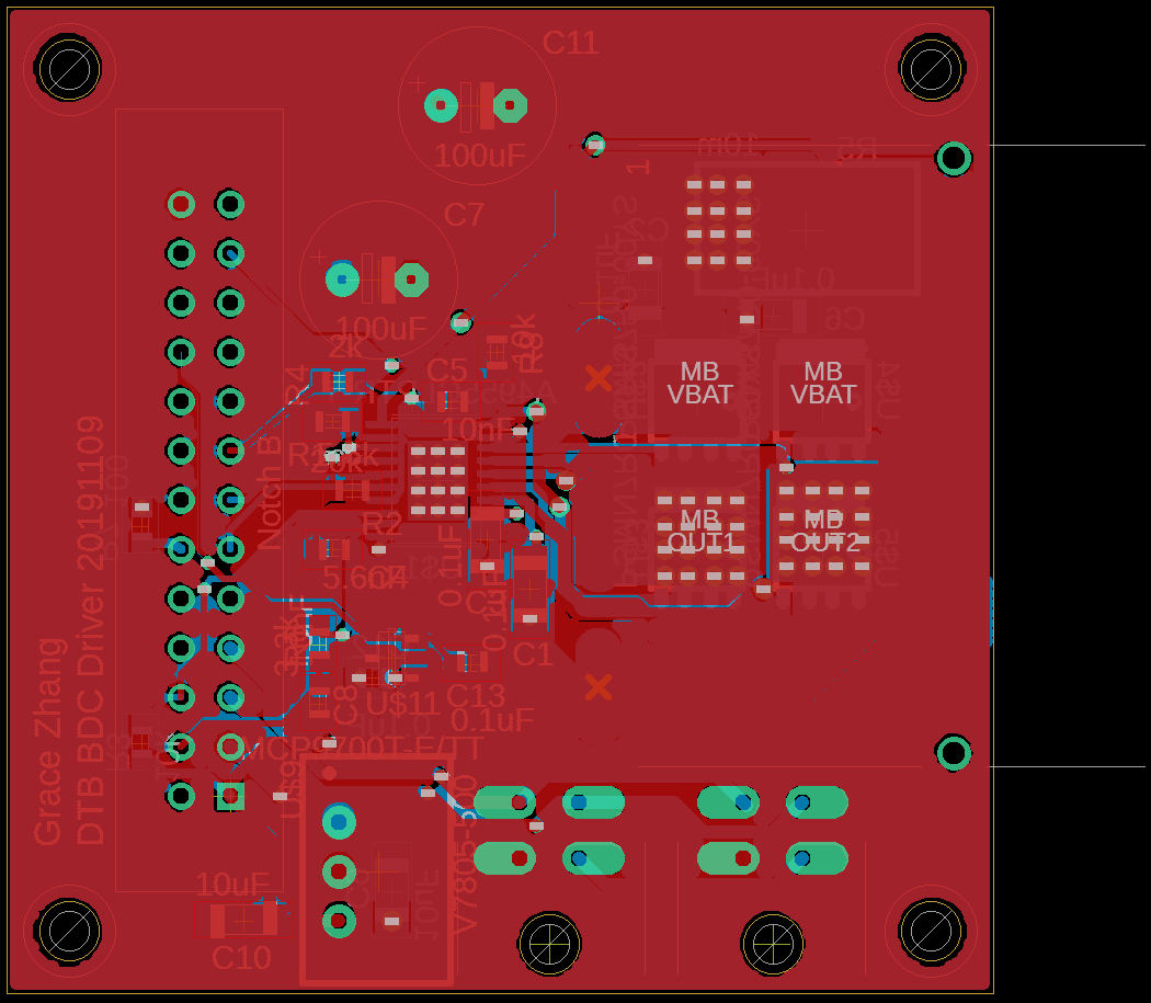
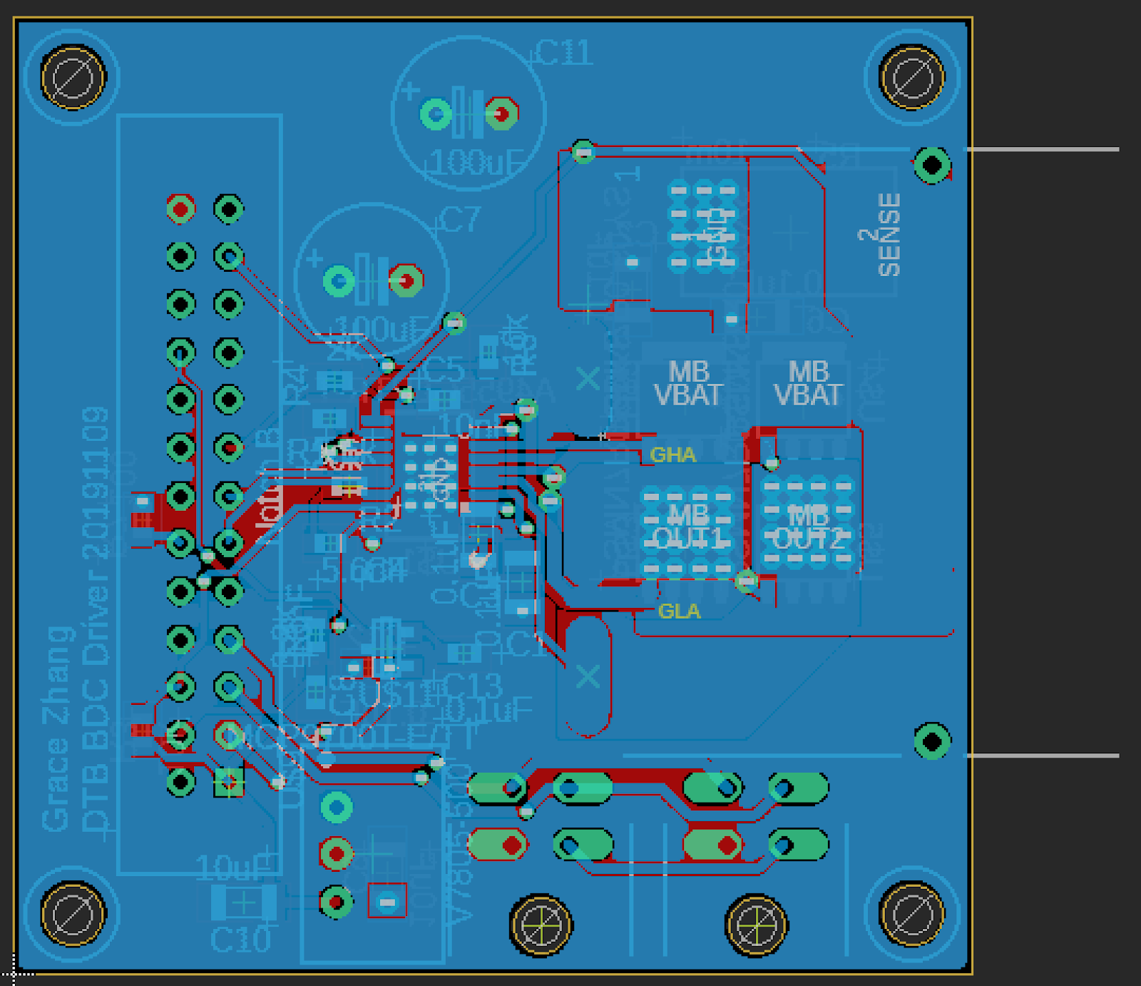
The layout had to be coordinated with the person making the logic board, since the two had to be stackable. The placement of components on the top and bottom sides also relied on their height; the taller components went on the top layer so that they would be sandwiched between the boards to reduce the overall DTB size. Since the board dealt with power signals, the power traces had to be short and thick, with lots of copper pours and vias to dissipate heat reduce electrical noise.
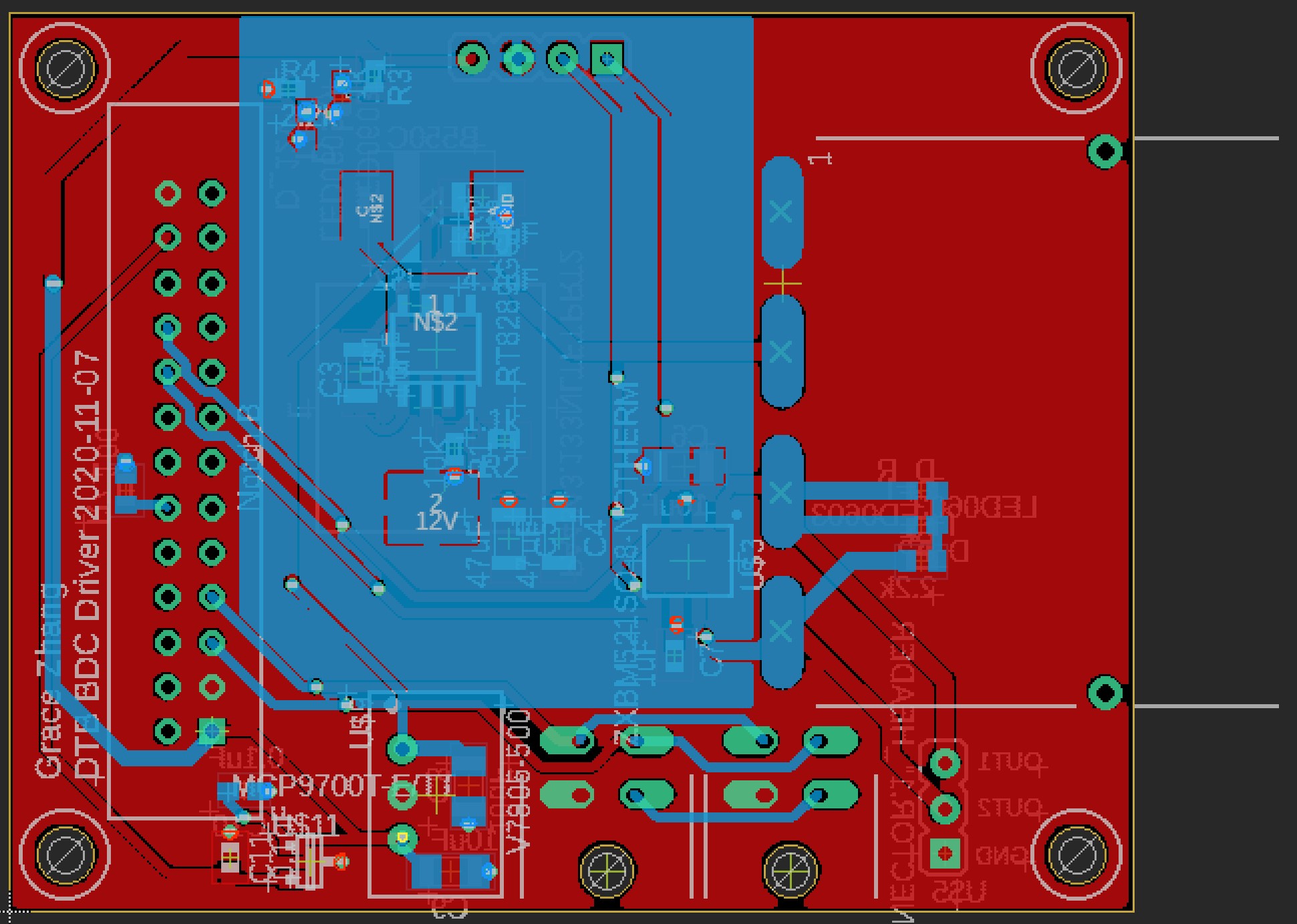
Final Design
The final design uses the A4955 as a motor driver. This provides gate drive for an external H-bridge made up of the N-channel FETs PSMN7R0-60YS rated for 60V and 89A. This H-bridge runs off the battery voltage of 20V-40V. Each of the FETs is controlled by gate driver signals from the A4955. There are large copper pours for the SENSE, OUT1, OUT2, GLA, GLB, GHA, GHB, VBAT, and GND to reduce noise. Additionally, the pours for OUT1 and OUT2 have arrays of vias to help with heat dissipation. These are all on the right side of the board, while the thinner signal traces are mostly on the left side of the board.
There are two Molex microfit connectors for CAN connections. These supply VCAN, GND, CANH, and CANL. While the power board itself does not use these, these connect to the logic board through the N2526-6002-RB connector. The pin configuration for this connector mirrors the connections on the logic board.
The power connections come from a powerpole connector. The powerpole connector also outputs OUT1 and OUT2 to the motor. These control the actual motor. Because of space issues, these slightly hang off the edge of the board.
2021-2022
In my senior year, I became the electrical subteam lead. Throughout the course of the year, I helped redesign the existing electrical system and oversaw the design and implementation of new systems. This included our custom brushless motor controllers, our boards for the Astrotech system (peristaltic pumps, CO2 sensors, spectrometry), and a new communication protocol between the electrical and software systems.